| History & Topics |
| Why Q Meter? |
 |
| The quality factor Q of an inductor
(or coil) is expressed by the ratio of the inductive reactance to the
coil resistance as Q=(2πf L) /R. At lower frequency where R stays constant,
Q is proportional to the frequency f. At higher frequency where skin
effect loss and dielectric loss of a coil are no more negligible, R
and Q become unforeseeable. That is why high frequency coils should
be measured at their intended high frequency, not at lower frequency
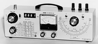
as 1 kHz. Prof. Frederick E. Terman of Stanford University described about the Q meter in his historical textbook of the electronics "Radio Engineering" in 1940s. Since then, Q meter has been one of the most important equipment to evaluate high frequency inductors. Although more sophisticated gear such as HF impedance analyzer now took place for the measurements, good old Q meter still exists in the electronics field rather than in the science museum. The principle of the Q meter is based on the equation of L and C parallel resonance. One can calculate unknown inductance (L) if frequency (f) and capacitance (C) are given. Q meter contains variable calibrated capacitor to tune through the resonance with the unknown L. If frequency is fixed properly, unknown L is read from calibrated L scale. Although concentration and certain skill are required to read Q from meter peak by fine-tuning the C dial, and determination of decimal place for L reading, the results are dependable as million-yen impedance analyzer. Q meters 651/661 are modern, compact and low-cost equipment with digital frequency display. The high resolution of the frequency display contributes to their accuracy. Those who know the hefty "boat-anchor" Q meters will be surprised to see them.
|
| History & Topics - INDEX |
| DELICA MITA MUSEN KENKYUSHO LTD |